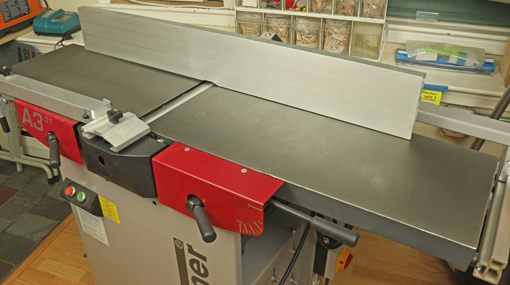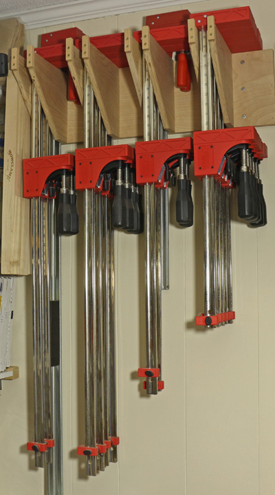
Archive for the Category ◊ Tools and Shop ◊

Author:
• Wednesday, November 05th, 2014

Jet clamps

What task produces some of the tensest moments in woodworking? Gluing up, right? And what are the main tools we use for that task? Clamps. Yet there usually is not much discussion about them, many woodworkers skimp on them thinking they’re not real tools, and they generally just don’t get much respect.

Let’s start with long clamps – bar clamps, carcass clamps, whatever you want to call them – that are mostly used to edge glue boards, clamp post and rail assemblies such as for a table, and glue up carcasses. This discussion refers to clamps where the contact part of the head starts right at the bar; not F style clamps.

I used 3/4″ pipe clamps for this for a long time – too long. They have the advantage of economy, especially because longer clamps are made by simply swapping the heads onto longer pipes. However, even with special supports and pads, they just cannot be used with the same reliable precision as parallel-head bar clamps.

Precision? For clamps? Yes. At crunch time, clamping precision matters. We use precision tools like squares, pinch rods, and straightedges to accurately assess a case or leg-and-apron assembly, looking for tiny gaps and misalignments. Doesn’t it make sense to invest in accurate tools to adjust and hold those parameters at the moment when it really counts and when there’s no going back?

As with most topics on this blog, I will tell you what I use and why, hoping this will be helpful to readers making choices and solving problems in their shops. I cannot offer comprehensive comparative reviews like in the magazines, just real stuff from years in my shop.

My favorite parallel clamp is the Jet. Bessey also make excellent clamps – I have some of their older model – and there are others including Jorgensen and Irwin. An alternative is the aluminum bar clamp by Universal Clamp Company, which is a precise clamp with the advantage of much lighter weight. Though a good choice for lighter work, these eventually lost out in my shop to the more versatile Jets, which are more rigid and deeper.
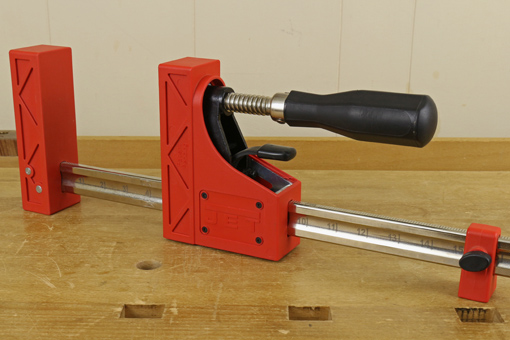
Jet clamp

To open the Jet clamp, the head is released to slide freely without catching by lightly pulling up on a lever under the handle. The head can be advanced to close the clamp without using the lever. I really like how the thread action engages immediately when the head is set into position. There is no lag or confusing need to lift or lower the handle for any of this.
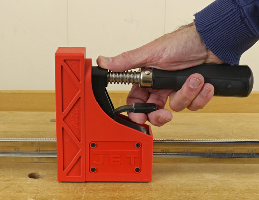
opening the Jet clamp

The long side of the firm, glue-resistant head extends more than four inches. In some situations, the work piece can also be placed on the side of the bar or under the short side of the head where there is about ⅝” extension. I like the large diameter handles that give good moment when tightening. To really sock down, use grippy gloves.

The inch scale on the bar is handy when readying a bunch of clamps, such as in edge joint glue ups. There is also a simple moveable support for the bar.

More to come on clamps and clamping.
Category: Tools and Shop  | Tags:  | 2 Comments
Author:
• Wednesday, October 08th, 2014

Chosera 10K

I guess I can’t quite leave sharpening alone. About six months ago I switched to using a Naniwa Chosera 10,000 as my primary finishing stone.

I had been using a Shapton 16,000 glass stone for this purpose and could have left well enough alone because it is an excellent stone. It’s fast, the grit is very consistent, it’s convenient because it requires no soaking, and it gives a great edge. However, the drawback for me has always been the lack of excellent tactile feedback from the blade on the stone surface.

This is particularly important for freehand or semi-freehand finishing of the cambered edge of plane blades where the feel of the edge on the stone is critical. Even when using a honing guide for simple non-cambered edges, the delicate feedback near the end of honing is helpful and reassuring that the angle and edge are right.

I had read reviews claiming the feel of sharpening on the Chosera 10K stone was outstanding and that is just what I have found. That’s the big difference and it really matters. Moreover, it cuts just as fast as the Shapton, maybe faster, but is practically more efficient because I have fewer do-overs. There is also no tendency for the blade to skip as on the fine Shapton.

The Shapton is 16K and the Chosera 10K, so does this mean a step down in edge quality? Grit number is just one factor is producing edge quality. Others include the particle shape and how it fractures, the consistency of particle size, the density of the particles and how they present at the surface, and the properties of the binder. In practical shop use, the Chosera has been producing edges not one bit less sharp or otherwise of lesser quality than the Shapton. In fact, I think it’s better, if only because I can better feel those last whispery kisses of the sharp edge on the stone to get it just right.

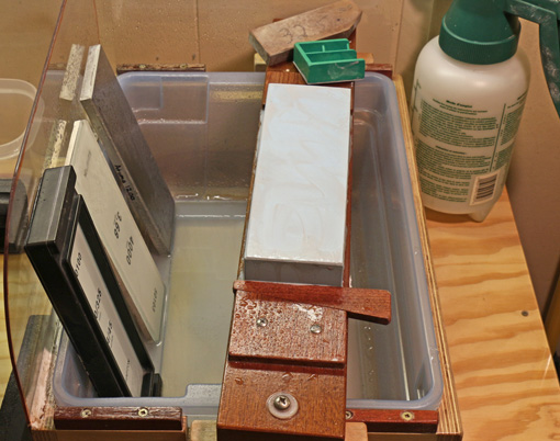
The minor downside of the Chosera is that it needs pre-soaking. Various recommendations can be found for this including that soaking is optional. I’ve found it needs 15 minutes. Less soaking, 5 or 10 minutes, makes the stone too quickly drink up the water you splash on when starting to sharpen. When finished sharpening, I flatten it while it is still wet with the Shapton diamond lapping plate.

I still use a 1200 grit diamond stone as a nagura and remain convinced this enhances the action and feel of finishing stones including the Chosera 10K, as well as the quality of the finished edge. (More to come on this soon.) I did not find helpful the nagura that comes with the Chosera.

This is an expensive stone but at more than one inch thick, it will last a long time. The bottom line is that it has made my sharpening more assured because of the excellent feel.

Author:
• Tuesday, September 16th, 2014

hand planes

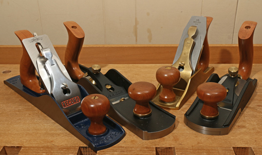
With their new line of customizable hand planes, Lee Valley/Veritas continues their impressive record of innovation in woodworking tools. Within each plane size, you can choose the blade steel, the handles (thankfully), and the frog.

The most compelling option, in my view, is the choice of frogs, and particularly in a smoothing plane. This gives us yet another way to vary the attack angle. This is simply how high is the angle (from horizontal) of the top surface of the blade at its very edge. In other words, it is the angle at which the blade meets the wood. This is one of several factors, a critical one, in reducing the dreaded tearout of hand planing.

Let’s look at the mainstream options for attack angle that we’ve had so far

In bevel-up bench planes, the blade is usually bedded at 12°, though I continue to assert that 20° – 22° would be better. The attack angle is determined by the bed angle plus the sharpening angle of the most distal bevel, usually a secondary or micro bevel. For example, a blade with a 38° secondary bevel sitting on a 12° frog, gives a 50° attack angle.

By maintaining multiple blades or re-honing a single blade, you have your choice of attack angles. By the way, because the wear occurs more on the bottom surface of the blade, the Charlesworth “ruler trick” is especially helpful when sharpening bevel-up blades.

In bevel-down planes, most are made with 45° frogs but Lie-Nielsen offers a choice of 45°, 50°, and 55° frogs for most of their great bench planes. I like the 50° frog in my L-N #4 smoother. The attack angle in a bevel-down plane is usually determined simply by the bed angle. The nifty exception is the back bevel, which is a tiny bevel on the (otherwise) flat side of the blade. For example, in addition to conventionally sharpened blades for my #4, I keep one prepared with a 10° back bevel to produce, with the 50° frog, an attack angle of 60°.

What’s new

Now Veritas, with their awesome manufacturing capabilities, offers a full range of bevel-down planes with your choice of frog angle from 40° to 65° in 0.5° increments. Furthermore, extra frogs can be ordered that can be easily swapped into your plane. So, you could outfit your #4 smoother with a 45° frog and an O-1 blade for a project in pine, then swap over to a 57.5° frog and a PM V-11 blade for a project in figured maple. The caveat is, of course, that I haven’t used these new planes so I cannot judge if their innovative design actually performs well at the bench.

All of this means we have more choices and a greater, though happier, burden of choosing. Obviously, each of us does not need or want every tool and option available, so it is more important than ever to make intelligent choices in tools.

Category: Tools and Shop  | 2 Comments
Author:
• Tuesday, August 26th, 2014

jointer knife alignment

Let’s explore a simple method to verify the alignment of jointer knives, which is necessary when changing or adjusting them.

The first goal is to have all of the knife edges across their full widths in a consistent relationship to the outfeed table. The top of the arc of the knife edge should be very slightly above the level of the outfeed table. Secondarily, perhaps after the edges wear down or the jointing performance needs adjustment, the overall height of the outfeed table can be tweaked.

There are several good approaches to dealing with this, some involving dial indicators and specialized accessory equipment, but I prefer a low-tech method. Though well-known, how accurate really is it?

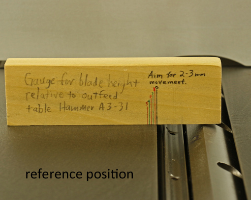
Here is how I perform the test, starting with unplugging the machine. A block of wood, about 3/4″ thick x 1 1/4″ x 4 ½” long is carefully jointed (by hand) and marked with 1 mm gradations. As you can see, I like to label the jigs I make with a description and reminders. It is placed in a reference position on the outfeed table (photo above, at top).

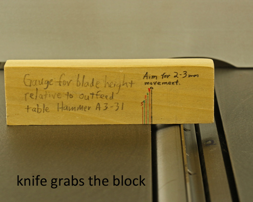
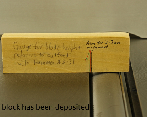
Then, the cutterhead is carefully rotated by hand to allow the knife edge to “grab” the block and advance it through the portion of the edge’s arc that is above the level of the outfeed table. The block is deposited as the edge “lets go” and continues its arc below the level of the outfeed table. (Photos below.) Note that a wooden test block is better than a metal ruler, which the edge doesn’t grab well.

jointer knife alignment

jointer knife alignment

The beginning and end of this arc define a tiny chord of the knife flight circle. The height of this chord is the amount of projection of the knife edge at its highest point above the outfeed table. The test is repeated at three or four places across the width of each knife.

Now let’s correlate this height with the lateral travel of the test block, which is the length of that tiny chord. A mathematical formula involving the Pythagorean theorem gives the results, tabulated below, for the 72 mm cutterhead knife flight circle on the Hammer A3-31.

Knife

Projection       Chord          Chord

(inches)          (mm)          (inches)

.0005             1.9             .075

.001               2.7             .106

.002               3.8             .151

.003               4.7             .184

.004               5.4             .213

.005               6.0             .238

.006               6.6             .261

The method is very accurate! A mere .001″ of knife projection moves the block 2.7mm, which is easily distinguishable from no movement, which signifies no projection.

However, note that the relationship of the knife projection to the advancement of the test block is not linear. The first thou of height advances the block 2.7mm – about 3mm. However, a height difference from .002″ to .003″ only advances the block about one more mm (0.9mm).

Fortunately, I want the knives to be a only about one thou, two at the most, above the outfeed table so all I have to do is see that the block advances about 2-3 mm, or 4mm at the most, and do so reasonably consistently across the blade width, for all of the blades. Indeed, the Hammer manual recommends 2-3 mm of travel.

So, there it is: a low-tech, accurate method. But now, after having analyzed it a bit, I have more confidence in it and can use it more intelligently.

Category: Tools and Shop  | 4 Comments
Author:
• Wednesday, August 20th, 2014

Hammer A3-31

This final installment in the series will discuss changing blades in the Hammer A3-31 and some summary thoughts on jointer-planer combo machines. [The entire series can be viewed here.]

With some jointers and planers, changing blades is a tedious chore. Long ago, I struggled with the old spring-loaded jackscrew system on a jointer. Brutal. By contrast, changing blades on the Tersa cutterhead that was in the Inca jointer-planer was almost unbelievably easy and fast. The OEM system on the Dewalt DW735 planer was quite easy, and now with the Shelix cutterhead with carbide-tipped inserts installed, changing blades is practically a non-issue.

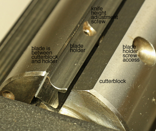
The system for changing and adjusting the blades on the A3-31 is very good, though not quite the slam dunk of a Tersa. Each of the three blades has holes that neatly register on bosses on the blade holder, which is secured in a slot in the cutterhead with four hex socket screws using the provided T-handle wrench. (See the photo above.) This is easy to do, though a cutterhead lock would make it easier.

If necessary, the blade holder-blade assembly can be adjusted for height with the four adjustment screws within the holder block. These can be used to make a consistent projection of the knife in relation to the outfeed bed across its full width. Further, the height of the outfeed table is adjustable to set its overall relationship to the arc of the knife edges.

The factory settings, which I assessed when the machine was new and the knives were fresh, were excellent; no changes needed! So, when I installed replacement knives, everything should stay the same, right? Well, it worked out pretty well, maybe actually well enough, but not quite to my satisfaction. Somehow, despite great care on my part, gremlins sneaked in and I had to fiddle with the height adjustment screws to get an a consistent projection across the width. (This is not a matter of a difference in the overall projection related to worn versus fresh knife edges.) The manual explains a simple assessment procedure to help get it right and I am happy with the results. Note that perfection is not necessary for this. By the way, another option is the helical insert cutterhead available for the A3-31 from Hammer.

Here’s the key: the machine performs accurately, consistently, and efficiently. I get the results I need to make high quality things from wood. This is what matters.

In summary:

1. For the reasons explained in this series, I highly recommend a 12″ jointer-planer combination machine for the small shop woodworker.

2. After 2 1/2 years experience with the Hammer A3-31, I heartily recommend it. As with any machine, there are a few shortcomings (for this fastidious woodworker), which I’ve covered, but this is an excellent machine that can be a great partner as you pursue excellent woodworking. I cannot fairly compare it to corresponding offerings from Minimax, Jet, Rojek, Grizzly, and Rikon because I haven’t used them, and I’d bet the $7,000 Felder AD-531 outshines all of these, but I can say I’m very glad I have the Hammer A3-31.

Author:
• Wednesday, August 13th, 2014

Hammer A3-31

Now for a look at the parts and systems of the Hammer A3-31 that can be adjusted and tuned, with particular consideration to the ease, accuracy, and durability of the adjustments.

Jointer beds

When the machine arrived, the beds were slightly out of parallel to each other across their widths (i.e. in twist) – by .006″ over the 12″ width. Not bad, but having seen the potential in the excellent flatness of the beds, I wanted to improve their alignment.

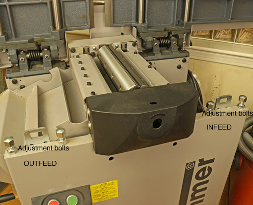
Since the alignment of the outfeed table to the knife arc was fine from the factory, the twist was easily removed by adjusting only the two bolts (see the photo above) on the operator side of the infeed table to make the tables parallel within .001″.

Next, using a long straightedge, I determined that the infeed and outfeed beds were tipped along their lengths toward each other. The gap at the middle was 0.018″. To my mind, this is like have a concavity along the full length of a jointer plane sole and would make accurate jointing difficult at best.

Again, the correction was made by adjusting only the infeed table. This was a more complicated adjustment involving the pair of bolts on the operator side and a pair of setscrews, accessed under a removable panel, on the hinge side. Each of each pair of screws must be adjusted by a different amount. To make a long story short, I did a little trigonometry to prevent having to do it by trial and error. The result: cha-ching! The beds are parallel along their length within .001″.

Unfortunately, the Setup Guide, which covers these adjustments and is available as a pdf on the Hammer website, is out of date (copyright 2005). It references an earlier design of the machine and much of the adjustment parts have changed. Fortunately, Hammer makes knowledgeable technicians available by phone who were generous with their time in helping me understand the machine.

I called Hammer this week in anticipation of this post, and they favorably received my suggestion to update the Setup Guide. The User Manual, included in print with the machine and also available online, is more current and clearly explains assembly, basic adjustments, operation, maintenance, and so forth.

Planer bed

I tested this on a performance basis by planing an 11 3/8″-wide board, and by planing two narrow sticks simultaneously sent into the planer at the outer width of it. From the factory, the planing parallelism was within one thou. Wow! This is adjustable if ever needed.

Digital handwheel

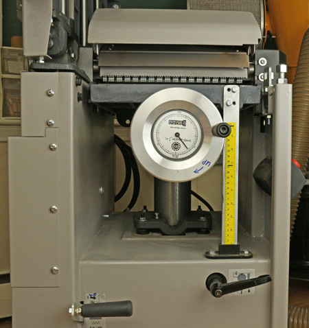
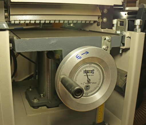
This accessory, which I have found very helpful, was calibrated using the information in the Setup Guide. Reading it takes a bit of getting used to because the numerals indicate decimal inches while the hash mark increments are actually metric that approximates imperial. It is really not a problem though.

Hammer A3-31

Fence

Setting up the fence accurately went according to directions, though it does take some care. To maintain a consistent angle, it is important when adjusting the side-to-side position of the fence in use to hold the sliding bracket down firmly on the extruded track while tightening the knob.

In summary, the A3-31 can be tuned to a high degree of accuracy. There are some finicky steps for those who want to tune it really well. Some documentation is lacking but help is available.

The most welcome feature is that the adjustments hold solidly over time and when converting back and forth from jointer to planer mode. This is invaluable.

Next: one more installment – knife changing and an overview.

Author:
• Friday, August 08th, 2014

Hammer A#-31

Let’s take a detailed look at the Hammer A3-31.

When considering a new machine or any tool, I first assess the quality of the key parts that cannot be altered by the user but are accessible to direct evaluation. Here’s how the A3-31 stacks up in this regard.

1. Bed flatness is excellent. Against a Starrett straightedge, the jointer infeed table is within .001″ along its length and .002″-.003″ on the diagonals. The outfeed table is just a hair concave along its length, .003″-.004″, and the diagonals are off by only .002″-.005″. The planer table is within .002″ along its length and .003″ on the diagonals.

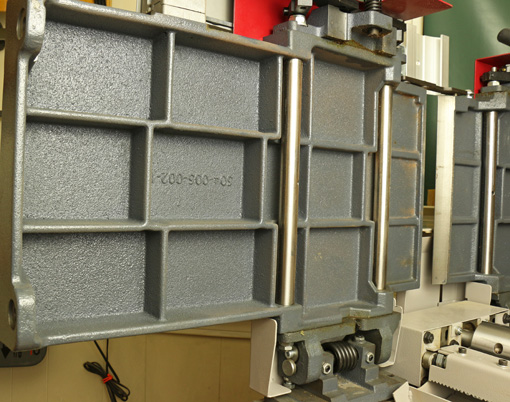
This all is excellent, well within Hammer’s spec of .006″, and is an important factor in how accurately the machine can be tuned. Furthermore, the beds are heavy and constructed with thick ribbing, as seen above.

2. The planer feed mechanism does not balk with 12″ wide boards. The steel drive rollers control the board unyieldingly, yet the indentations made by the infeed roller are shallow enough to disappear when the final pass is very light. With good technique, snipe is about as minimal as it gets.

The feed speed is 6.5 meters/minute (21.3 feet/minute), which makes the three-knife cutterhead at 6000RPM produce 70 cuts per inch, typical for jointer-planers in this class. Compared to the DeWalt 735 (with a stock cutterhead) at 96 cpi in “dimensioning” mode and a phenomenal 179 cpi at the slower “finishing” feed speed, the A3-31’s 70 cpi may seem a bit rough but in fact it seems to strike a good balance between producing an excellent surface and working at a good pace.

Hammer A3-31

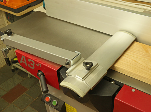
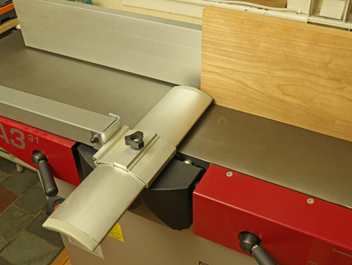
3. I like the Euro-style safety guard better than the spring-loaded “pork chop” style. I always use paddles for face jointing and it is easy to pass the board under the narrow guard, which is height-adjustable using the knob at the far left in the photo below.

Hammer A3-31

For edge jointing the guard can be adjusted laterally to expose the minimum width of cutterhead. It would be better if the guard was hinged so half of it would hang down when it is adjusted very far toward the user side of the machine – but it’s not in that position too often so it hasn’t been a problem. The hinge feature is present on the company’s higher priced models.

Hammer A3-31

4. Dust collection, as I mentioned earlier, is just wonderful, for jointing and planing. This helps a lot in my small shop.

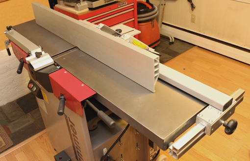
5. The construction of the aluminum fence makes it very stiff. It is flat within .001″ in all directions and I cannot detect any twist. It is adjusted back and forth by using the knob (to the right in the photo below) and sliding the bracket on the extrusion track.

A slight complaint is that the squareness of the fence to the table cannot be made exactly consistent throughout its full adjustment range and most of its length, probably due to minute errors stacking up. However, the discrepancies are quite small, and by finding favorite locations for the fence, I have had no problem getting nice square edges on long boards.

Hammer A3-31

From the back view, you can see that not much sticks out – only the rear cutterblock cover. For most fence positions, the net depth of the unit is about the same with the jointer beds down or raised.

Hammer A3-31

Other key components that I cannot directly assess seem very good based on indirect observations and working with the machine. Machining and part formation looks neat throughout, with no ill-fitting components. The motor has excellent power and does not get overheated. Hand adjusted parts, such as the planer bed adjustment are very smooth, and the machine runs with that nice low hum suggestive of quality.

The same outfit that makes Hammer machines also makes the much more expensive Felder line. A Felder 12″ jointer-planer lists at over $7000 (ouch, my hand just cramped up at the keyboard), which is more than twice the price of the Hammer A3-31. I figure that the expertise and institutional experience applied to the Felder line must bleed over into the Hammer line. I’d bet it’s more than half the machine for half the price.

Next: The final next installment in the series will cover tuning and results.

Category: Tools and Shop  | Tags:  | Comments off
Author:
• Thursday, July 31st, 2014

Hammer A3-31

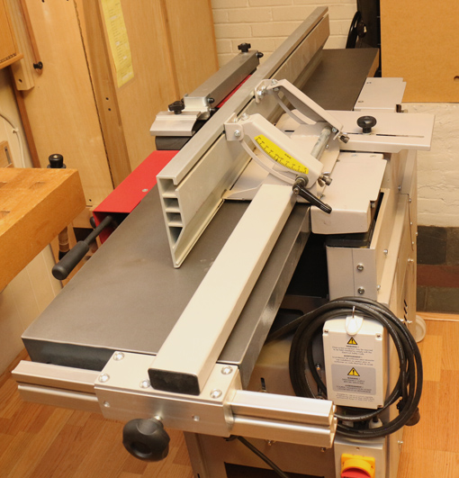
Having established in the previous post a rationale for this type of machine in a small woodshop, let’s take a look at the Hammer A3-31, which I’ve been using for the past two and a half years.

Getting it into the shop

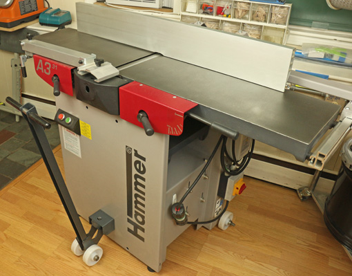
I’m afraid I must start with one of the few problems I have experienced with the A3-31: getting it into my shop. The mobility kit uses a single axle that attaches to the base parallel to the 55″ jointer bed, along with 4″ wheels that simply turn in one plane – they do not swivel. A lifting bar is inserted into a cleat near the bottom of the base of the machine to roll it in a straight line and make partial J turns.

The top photo shows the lifting bar in place. One wheel is visible at the lower right of the machine base.

The system works well in the shop but it will not get the machine through the 32″ doorways in my house or the 36″ doorway of my shop. To make matters worse, the A3-31 was shipped on a pallet built for a special narrow-fork pallet jack. I ended up having to transfer the machine from the pallet onto a dolly that I built and use plywood sheets to get it over doorway bumps – a big hassle. If you have a garage shop or other wide doorway, all of this is not a problem.

To solve this problem, I wonder if Hammer could include a short axle to attach to the base perpendicular to the jointer bed to be used with a matching cleat. It might work only with the jointer beds raised but that would be good enough to just get the machine through narrow doors. Hey, Hammer: this would help many small shop woodworkers.

Now on to happy issues.

In order of frequency, here are the most common concerns among woodworkers that I’ve heard and read about j-p combo machines:

1. Changing between jointing and planing modes.

Fuhgeddaboudit. To go from jointing to planing, the fence stays in place. You lift the jointer beds as a unit, then flip the dust hood and reattach the hose. The tables remain parallel when raised so the effective width of the machine is approximately unchanged. The planer bed is cranked into position with an extremely smooth and fast mechanism. The jointer beds return to position precisely. Really, it’s all fast and easy.

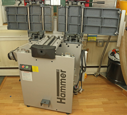
Here are the beds lifted:

Hammer A#-31

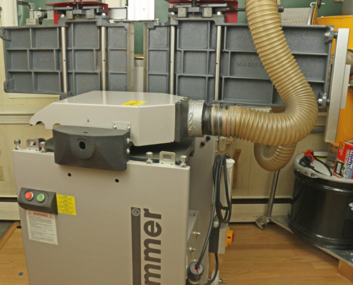
And here the dust hood is in place for planing with the hose attached:

Hammer A3-31

This is the planer infeed with the bed raised into place. The adjustment mechanism has the helpful, optional “digital handwheel.”

Hammer A3-31

2. Jointer bed length

Is a 55″ jointer bed long enough? It sure is for anything I do. I have no problem routinely accurately jointing rough boards 6′ long. In my opinion, there is no need to have the entire board length supported on either the infeed or outfeed table to do accurate jointing.

If you want more length, Hammer offers optional extensions for jointing and planing that look like they attach very easily.

Hammer A3-31

3. Dust collection

Can the dust hood contraption really work in both jointer and planer modes? Yes! The A3-31 is nearly perfect when used with my Oneida Mini Gorilla cyclone collector. It is the tidiest machine I’ve ever used.

4. Accuracy

Can a combination machine be as accurate as single function machines? This was my number one concern when contemplating the purchase.

For a given quality level, having used the Inca for many years, and now the Hammer, I say the answer is yes. I did have to do considerable work tuning the A3-31 to my liking but I’m a rather fastidious worker. (“Really, Rob? You? Get outta here, I wouldn’t have imagined . . .”) The key is that this machine can be tuned and it holds the settings. More on this in a future post.

5. Power and mass

Are these machines, in this size range, just toys for dilettantes? OK, now I’m getting a little annoyed. Just fuhgeddaboudit, OK? The motor is listed at 14 amps/220V and does not balk at planing full width boards. The mass of the beds, the quiet operation, and the results it produces are real deal.

[This extended review of the A3-31 and the general topic of j-p combo machines are unsolicited and uncompensated.]

Next: getting inside the machine.