More quick tips to bring the total to 65 in eight posts.
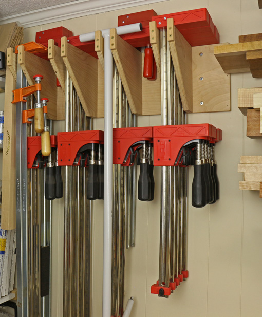
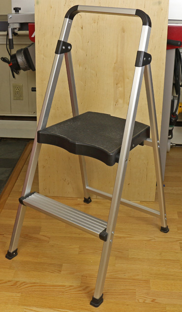
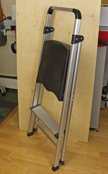
Placing and removing heavy boards while reaching overhead to high lumber racks is a danger we do not need. I feel a lot safer on the large platform of this very lightweight stepladder. With a platform height of 21″, it folds flat for storage, securely locks into its open position, and has a top crossbar that you can hold on to. It now comes with a tool tray at the top and taller models are also available.
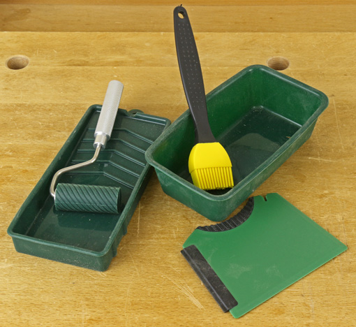
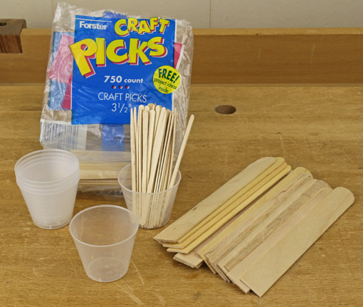
Tongue depressors can be handy glue applicators but only if the rounded ends are sawn flat. It is easy to clamp a bunch together and saw the ends square or, if you like, at an angle. When I need a narrower applicator, it is easy to split one lengthwise with my fingers. For smaller work, the craft picks are good. For small, multiple joints like dovetails, glue up goes faster by filling up one of these little cups with glue and withdrawing blobs rather than repeatedly fussing with the glue bottle.
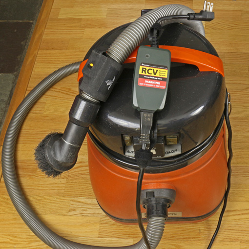
For vacuuming furniture parts between grits while hand sanding, as well as for certain other intermittent vacuuming tasks, I got tired of over and over reaching for the switch on the shop vac. Now I love this rig made by FastCap. The receiver plugs into the outlet and receives the shop vac plug. The small remote with an unobtrusive yellow button slips into a hook-and-loop collar that can be secured anywhere you prefer near the vac nozzle. The shop vac main unit stays out of the way and the work goes faster.
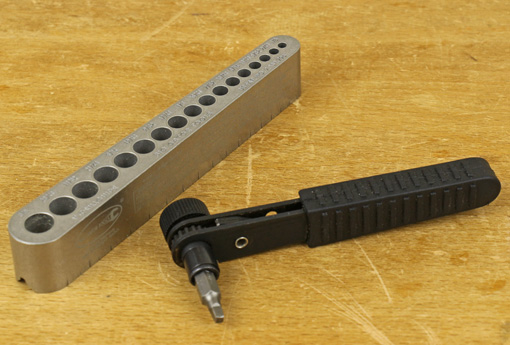
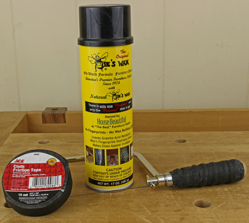
Most slick varnished wooden tool handles make no sense and are a pain. The hockey stick handle wrap is an excellent remedy, demonstrated here by a real hockey guy. For tool handles, I found it better to precede the raised helical wrap with a base flat layer. The cloth friction tape that I’ve mentioned in other posts works well for this. He saws, he scores!
When you don’t want friction, this spray beeswax is a pleasant, natural alternative and very handy to apply. Thanks to saw maker extraordinaire Mark Harrell of Bad Axe Toolworks for this idea.
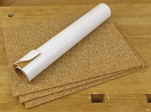
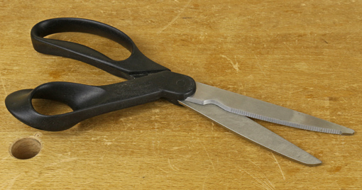
Woodworkers need to cut things besides wood, often fairly heavy things like brass shim stock, cork sheet, plastics, and so on. A tough pair of scissors with one lightly serrated blade manages this work without being overwhelmed and slipping like kitchen scissors with smooth blades, and are still fine for light work. These by Fiskars are old but Wiss model #W912 appears similar.
Remember, 65 quick tips in 8 posts can be found in one place, via the Series Topics link list.