Archive for the Category ◊ Techniques ◊

Author:
• Thursday, October 31st, 2019
long grain shooting

Long grain shooting does not get the attention this valuable technique deserves. A cousin to end grain shooting, it is just as simple in principle but more so in practice. 

We are simply planing straight and square along the long grain edge of a board by laying it flat, elevating it, and using the plane on its side, which must be accurately square to the sole.

In general, this is most useful for workpieces about two feet long or less. This stock is often fairly thin, and may also be narrow. A good example is preparing quartersawn pieces to glue up for small to medium drawer bottoms.

It is difficult to balance a plane on the edge of a workpiece thinner than about 1/2″ held in the front vise. Shooting is a much more stable setup, and still allows a good sense of the nuances along the edge – straight or cambered. (An alternative is to plane two or more boards at once in the front vise.)

All you really have to do is lay the board flat on a support board with the long edge of the workpiece slightly overhanging the edge of the support piece. The sole of the plane is therefore riding only on the work piece, unlike with end grain shooting. In fact, a minimalist setup could be to just place a support board underneath the workpiece, and clamp the pair to the workbench, upon which the side of the plane will ride.

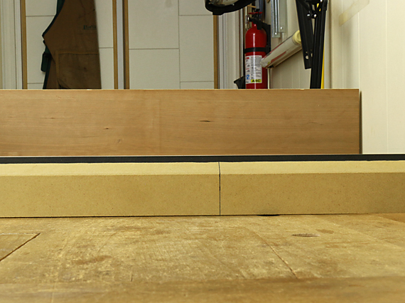
I use a dedicated long grain shooting board (below) that accommodates work up to about 24″ long. (Long time readers may recognize that it has been modified from its former role in end grain shooting.)

shooting board for long grain

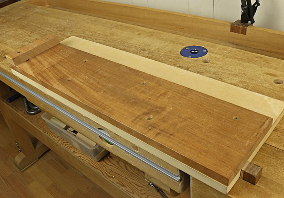
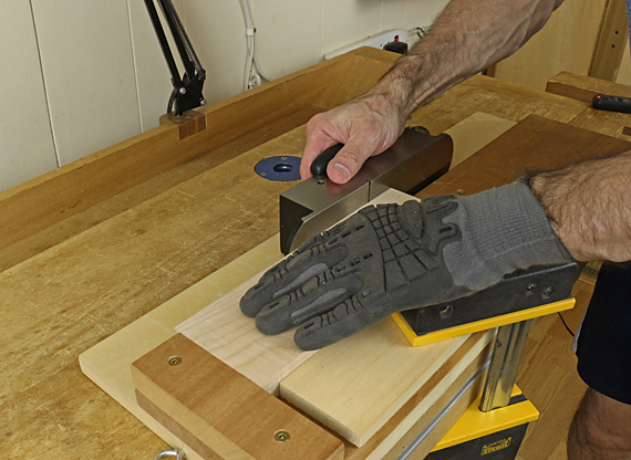
This arrangement allows me to reach over the workpiece and plane the edge that is facing away from me, which creates similar body mechanics to the usual way of pushing a plane. The PSA-backed UHMW slick plastic installed on the plane track makes the work easier.

long grain shooting

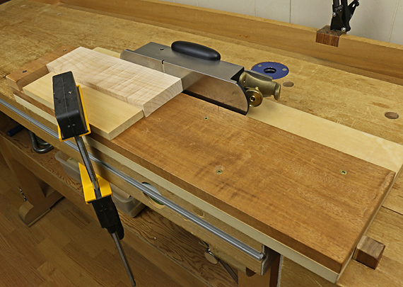
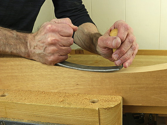
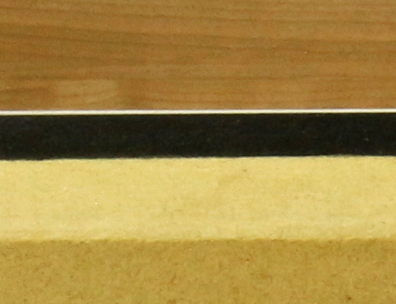
The workpiece (the curly maple in the above photo) must be controlled in all directions. For lateral control along the length, I use an ad hoc arrangement with a scrap board clamped to the near side of the shooting board. Alternatively, you could make a more elaborate jig with a wider, permanent, adjustable, screw-mounted lateral-control board on the side away from you, and plane the edge facing you. This seems awkward to me.

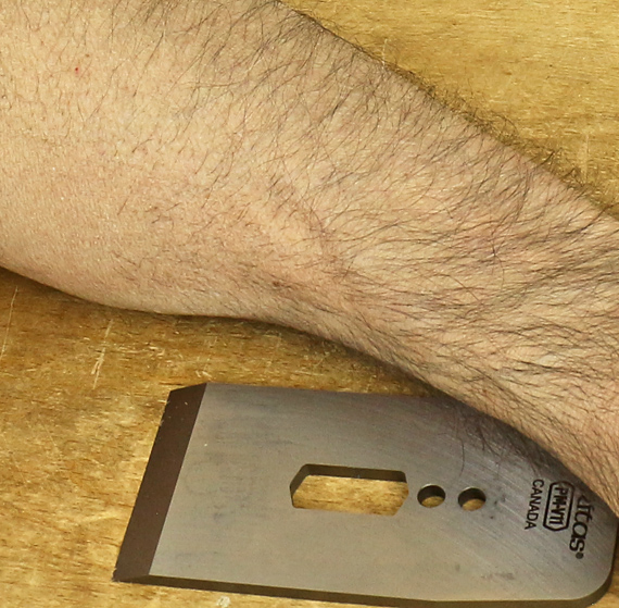
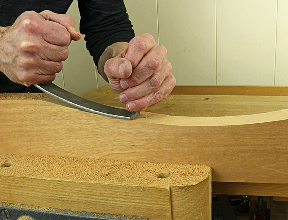
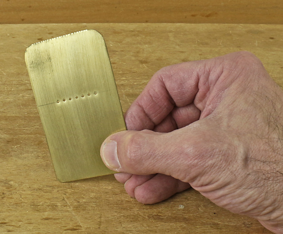
The end of the workpiece meets the front stop. Ideally, this is a square meeting but that is not essential. Mild downward pressure on the workpiece is supplied by you. You may be able to get away without using the clamp and lateral stop board for small pieces. I find the grippy glove (top photo) makes the work easier for all setups, small or large, clamped or not.

There is no reason to over-complicate this technique. Keep it simple and use it often. 

Next: planes for end grain and long grain shooting.

Category: Jigs and Fixtures, Techniques  | Tags:  | 2 Comments
Author:
• Monday, September 30th, 2019
sharpness tests

Knife Grinders is one very serious bunch of sharpening experts. Located in New South Wales, Down Under, their website is full of interesting information. What particularly caught my interest is their detailed list of sharpening tests that can be done with simple equipment, notably hair. 

I recently posted about the sharpness tests that I use, but these guys have refined things to an ethereal level. Caution here, it bears repeating: the only fully meaningful tests of a sharpened edge are its performance and endurance in its assigned task. We also must consider appropriate edge geometry and endurance.

But check out the Knife Grinder’s list. I like the arm hair shaving gradations on page 1. The hanging hair tests (pages 4-5) are intense. 

Maybe you think this is fetishizing sharpening beyond practical woodworking. OK, maybe it is, but it is nice to know that there are convenient, fairly standardized ways to test how your sharpening procedures are performing. To get scientific, one could get a BESS tester from Edge On Up

You probably have your own sharpness tests but I suggest taking a look at that list. It’s pretty cool. 

Category: Techniques  | Comments off
Author:
• Wednesday, March 06th, 2019
sharpening plane blades

Sharpening is so much at the core of hand tool woodworking, and so here are a few thoughts that build on the previous post on sharpening tests.

1. Can we close the loop and say that the proxy tests are actually validated by the tool’s performance? Based on experience, yes, regarding sharpness, edges perform as the tests predict. The tests are worthwhile.

2. Edge endurance, however, is another matter. There you are relying on the “design” of the edge and the reliability of your sharpening process. The only “test” is over time – seeing how long the edge lasts. For good results, you must match the edge geometry to the steel and the task.

For example, A-2 is a good choice of steel for a jack plane blade but if the bevel angle is too narrow, such as would be good for O-1 steel, the edge will be prone to premature chip-out. 

As another example, a plane blade with a wide bevel angle (e.g. 43°), though correctly employed in a bevel-up plane to create a high attack angle to reduce tearout, will necessarily have a shorter useful working life than narrower edges.

3. Squareness or, as appropriate, the correct skew angle, is, of course, easy to test. By the way, I find that a chisel edge that is just a bit out of square is not a big deal, as is sometimes supposed. There’s also a bit of squareness tolerance in most plane blades.

4. For many woodworkers, the most vexing matter of edge geometry is plane blade camber. For choosing, producing, and assessing camber, I invite readers to visit this series of five posts, which is about as in-depth a treatment of the subject as I think you will find anywhere. 

Stay sharp, amigos.

Category: Techniques  | 5 Comments
Author:
• Sunday, February 24th, 2019
sharp edge

The only fully meaningful tests of a sharpened edge are its performance and endurance in its assigned task. Nonetheless, at the sharpening station it is convenient to use surrogate tests to evaluate the fresh edge. Even with high confidence in your sharpening procedure, it is helpful to ensure the edge meets your expectations before you put it to work. This is especially so for plane blades.

I do two evaluations. Most important, I look at the edge. The irony is that being able to see it means it probably is not good enough. 

Look almost straight on at the edge under a bright light, preferably with magnification, and try to catch a reflection off the edge. I use the large, low-power lens in the articulating art lamp at my bench. Play the blade under the light, searching for a reflection. If it is really sharp, there is none to see. This is difficult to photograph, but the O-1 edge shown above is about as pristine as it gets. The narrow secondary bevel and a few dust particles are visible but the edge is clean and invisible.

Examine all along the edge. It may be fine except for a defective blip that reveals itself by reflecting light. That may be acceptable for a mortise chisel but an unwelcome frustration for a smoothing plane blade going to work on pearwood. Below is a used edge with several obvious blips, even though the rest of the edge is pretty sharp.  

A2 steel chipping

Because the endpoint of this evaluation is a negative observation, and there are probably differing levels of sharpness within that, I like to also have some positive demonstration of the edge’s capability. 

My preferred functional test is to shave hair on my arm. I gently bring the edge up to just a few hairs. For a smoothing plane blade, for example, I want to see those hairs well-nigh pop off with minimal pressure. I find the amount of pressure needed to cut hairs is a good indicator of sharpness. Using hairs growing at different angles or of different stiffness can be even further revealing. With just a little experience, it becomes easy to reliably differentiate high levels of sharpness. After all, we intuitively use this sense all the time when shaving with a manual razor.  

If the edge performs well on the hair test and the sight test does not show defects, I’m happy with it. For easy sharpening jobs such as chisels, sure, it’s often adequate to just trust that my usual sharpening sequence produced a good edge. For almost all plane blades, however, I do test the edge visually and functionally before putting it to work. 

All of this assumes, by the way, that geometry of the edge is satisfactory – squareness, camber, and angles, as appropriate.  

Some woodworkers are comfortable with other tests. A good one is to pare the end grain of a soft wood. Little pressure should be needed to make a very thin, clean slice without collapsing the wood’s vessels. Practice will soon reveal how a very sharp edge acts in this test. 

Another method is to see how low an angle you can engage the edge as you slide it along your fingernail. I don’t like aiming a sharp tool toward my cuticle. The barrel of a plastic disposable pen is a better, safer test surface.

One method that I do not think is useful is to feel the edge by brushing your finger across (not along!) it. Yes, you can tell a really dull edge from a decent one but I do not find this is a good way to differentiate high levels of sharpness needed for woodworking.

Category: Techniques  | 3 Comments
Author:
• Friday, January 18th, 2019
RP rasp by Liogier

This rasp is unique: the toothed surface is flat across its width with a convex curve along its length, and handled at both ends. 

Grasp the handles intuitively – from the sides or over the top – and bring teeth near the leading end into contact with the wood (top photo), then ease the trailing part of the rasp onto the wood (photos below), using a pull or push stroke. Let the sharp teeth do the work; don’t force them into the wood. As you move along the desired curve, you’ll subtly feel more resistance over bumps, less over hollows.

curved rasp

This does not work like a compass plane or spokeshave because they have only one contact point that cuts. The rasp cuts all along its length, encouraging a sweeping motion

RP rasp

Curves are generally best worked in the downhill direction so as to work with the grain, but this can vary. I readily switch from a pull stroke to a push stroke as I work, gently tipping the rasp toward or away from me as needed. This tool encourages working instinctively.

The constant radius of curvature of the rasp makes all of this easy and intuitive. You can use any part of the rasp, changing from push to pull, and always know the curve you are presenting to the wood is constant. (Of course, this does not mean the rasp is restricted to working on curves of constant radius.) In my early designs for this tool, I found I could not work as fluidly with a variable radius. 

The stiffness of the rasp, the tang fit of the handles, and the smooth-cutting sharp teeth, magnificently crafted by Noël Liogier and his team, work together to provide excellent feedback to your hands as the curve takes shape under the tool. You can feel the curve becoming true even before you stop to look at it. 

I think you will be delighted with the performance of this rasp. Liogier sells it for €58, about $66, which is a bargain considering its durability, utility, and the incredible workmanship they put into it.

Category: Techniques, Tools and Shop  | Tags:  | 3 Comments
Author:
• Sunday, December 30th, 2018
clamping

You’ve cut your joints, fitted them individually, and happily found them to be tight and true. Now you dry assemble the frame or carcass, which should include applying the clamps to rehearse the conditions under which the glue will dry. 

Unfortunately, you may well find that despite the rightness of the individual pieces and joints, and having applied the clamp forces in true directions, the assembly is out of square, twisted, or harbors some other seemingly unmerited vileness with which you must now contend. 

What’s going on? Well, I suppose tiny tolerances, wood movement, unnoticed error stacking (and probably the alignment of the planets) have somehow militated against the righteousness of your assembly. As careful as I try to be, I find at least a little bit of this is not the exception but the norm. 

So, the next step is to tweak the clamp placements to true the assembly. For example, you can use pinch rods and recall the rule of the long diagonal.

But how much should you force the assembly into true? Consider that you are probably using several clamps, each capable of perhaps a thousand pounds of force, which can easily bend and twist wood. You may be truing one aspect of the assembly while distorting another, making it impossible, for example, to later get a good sliding fit with a drawer. 

Clamp force can also compress wood, especially on side grain where it meets end grain, which is part of most joints. I think a little bit of this nearly always happens in clamped glue ups and acts as an acceptable correction mechanism. Carried too far, however, I suspect it may show up next year as gaps at the joints because the glue line has some elasticity, especially with PVA glue, and the wood compression may not be fully elastic.  

The point is to not add too much stress to the final assembly by using clamp force as a correction mechanism. As much as possible, the components of the assembly should “want” to go together true, flat, and square. Very small corrections by clamp placement to true the assembly during glue up will likely not cause problems, but overwhelming a fundamentally untrue assembly with clamp force is not a good approach. Neither is making joints so loose that they can be easily forced into any configuration. 

If the assembly requires anything more than gentle correction with clamps, go back and tweak the joints and/or components if possible. As examples, judiciously trimming tenon shoulders will solve many frame constructions. Dovetail assemblies can sometimes be tweaked by planing the inside face of the tail board, or easing overly tight spots in the joint itself. 

Finally, keep in mind that you can also compensate for some imperfections in the glued-up assembly. For example, a slightly twisted frame-and-panel for the back of a cabinet can usually be easily held flat by the cabinet itself without significantly stressing the carcass. On the other hand, a slightly twisted cabinet door or box lid is difficult to fully correct directly, so it is usually easier to plane the front edge of the carcass (preferably before glue up!) to accommodate the twist in the door.  

Every situation is different, but the general principle is: don’t force it much! Try to use good stock preparation and joinery, make judicious corrections as needed, and think through how remaining imperfections might be accommodated. And maybe you’ll find the planets to be aligned in your favor after all.

Category: Techniques  | 2 Comments
Author:
• Monday, June 25th, 2018

perfection?

Accuracy of what?

You square the blade to the table saw surface – the setup. Looks perfect; you swear it does. But the workpiece is what matters – the outcome. So you take some test cuts, only to be swearing again, this time in a different way.

What going on? Well, your thinking is right. It is best to work as directly as possible. Assessing the test cuts is closer to the actual goal, which is to make a square edge on a piece of wood so it will fulfill its role in the project. The squareness of the table saw blade is one step removed from that goal.

Another advantage of relying primarily on outcome is that sometimes the error assessment can be magnified. Testing a crosscut for square is an example. The error can be doubled by pairing two cut ends together, or quadrupled by crosscutting around a rectangle.

In theory, a good setup should yield a predictable outcome. As Yogi Berra said, “In theory there is no difference between theory and practice. In practice there is.” Gremlins lurk in the table saw example and in nearly all such matters in the shop. Sometimes decent accuracy can seem impossible to achieve.

The problem is simple (kinda): there are other factors that come into play. You’ve made assumptions. Sometimes these are difficult to measure or account for. For major shop machines and most small power tools, the gremlins can usually be traced to these three key factors:

  • Table/surface flatness. There should be no dishing, no bumps, and no twist. Any defects should hopefully be where they do not matter.
  • Fence flatness. Fences need to be straight, but also without twist.
  • Arbor alignment and runout. The rotating part has to run true.

In the simple table saw example discussed above, perhaps you squared the blade from the left side, but rip cuts performed on the right side are a bit out of square. Check if the table is flat. As another example, imagine the error stacking that can result if jointer tables are twisted and/or bowed.

Looking at that list of three key factors, unfortunately, they are things that you cannot correct easily, if at all.  What’s the answer? Buy the best quality tools you can afford, and check them for good bones. That’s where cheap stuff usually falls short. Of course, other factors come into play but without these basics in order, it will be rough going. Do not be distracted by cute features that are added to make tools sell.

There’s one more issue. When trying to produce accuracy based on outcome assessment, it may be difficult to quantify the adjustments needed to alter that outcome. In other words, how much of a change in the setup will result in how much change in outcome? This happens a lot with the bandsaw. Sometimes trial and error is the best you can do. Sometimes it’s best to make the setup as good as you can and just go with that. An example would be making the table saw slot parallel with the blade.

The main points are:

  • Recognize the difference between setup accuracy and outcome accuracy.
  • Be cognizant of the multiple factors that may affect outcome accuracy.
  • Be aware of the common culprits.

Remember too, you’re going for excellence, not perfection.

Category: Techniques  | 3 Comments
Author:
• Monday, April 30th, 2018

winding sticks

As with any tool, especially a simple one, winding sticks must be used correctly to gain their full value.

The setup

Place the darker stick on the near end of the board or surface in question, and the white stick parallel to it on far end. Shine diffuse light on the far stick to improve the visual contrast between it and the darker near stick.

As much as possible, ensure that the sticks are placed on unambiguous surfaces. The assessment will not be meaningful if, for example, one of the sticks is placed on the convex side of a cupped board, seated on one side of the “hill.”

The vision

Understanding some basic optics can help you use winding sticks with ease and precision that you may not have thought possible. On this, I can speak with special expertise, but here are the basics that matter.

Regardless of the optical status of your eyes, it is impossible to simultaneously maintain a clear focus on the near and far stick, unless they are both within the “depth of field.” Think of depth of field as simply the range – how close to how far – where things are in acceptably clear focus.

You want both sticks in focus (i.e., within the depth of field) so you can compare their top edges. Therefore, you want to make that depth of field large. Just as with a camera, do this by using a small viewing aperture (i.e. the hole you look through), and/or don’t position yourself too close to the nearest object (in this case, the near stick).

Viewing technique #1 – at least do this

Position yourself at least a couple of feet back from the near stick. This will give you a better chance to get both sticks within your eye’s depth of field. (For many reasons, this varies from person to person, and with viewing conditions.) Experiment, but avoid getting right up to the near stick.

Viewing technique #2 – this is the cool one

Artificially make your viewing aperture very small by viewing the sticks through pinholes. This is usually described in other sources as viewing through a single pinhole. This does not work well because your view is not wide enough to see the full width of the sticks, forcing you to move your head side to side to see them. The inevitable inaccuracy in this movement will degrade the assessment of twist.

Instead, use a trick that I have been using for decades, and also published ten years ago in Woodworking magazine (an excellent publication that has long since folded).

Cleanly drill a row of about seven 3/64″ holes, 5/32″ apart on center, in a 3 1/2″ x 2″ rectangle of 1/64″-thick brass, or similar clean-drilling material. Round the corners of the piece for safety. The completed tool looks like this:

pinholes for winding sticks

Get your face to the level of the sticks. Hold the row of holes horizontally up to your eye, and sight the sticks. The rectangular shape of the tool will help you orient the row correctly. Both sticks will be in clear focus, and you can view their full widths. It is quite surprising once you see it.

I simulated the eye’s view with photographic technique in the photo at the top of this post. Note the thin white line of the far stick peeking up just above the black line of the near stick. The sticks are a few feet apart. (The cherry board in the back is there just to block out the visual confusion of the shop background.) The photo below is of just the left side of the sticks in a magnified but not resharpened view:

Accuracy and utility

Using the pinhole technique is easy and quick. It is very helpful for woodworking where accuracy is important, and, I think it is essential for assessing reference surfaces such as jointer tables.

You can test your system for accuracy by placing thin shims under one stick, near its end. Depending on your setup, you’ll probably be able to detect a difference between one side of the sticks and the other side of .006″, maybe better.

The approach to winding sticks that I’ve described in this and the previous post is a good example of using a simple tool well.

Category: Techniques  | 5 Comments