Author Archive

Author:
• Sunday, June 28th, 2020
DeWalt cordless sander

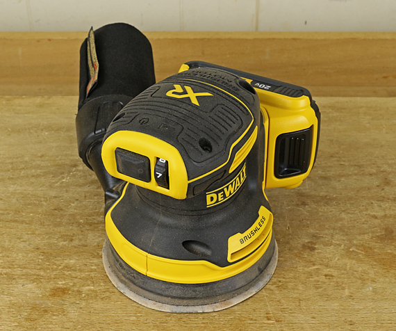
The DeWalt DCW210 is a cordless 5″ random orbit sander that is powered by the company’s 20-volt lithium-ion battery system.

Smitten with DeWalt’s 20V Max series of tools, it is a bit like dealing with Apple stuff. I know I’m being played but the products are just darned good. 

Handling is excellent. Weight, vibration level, and control are comfortable. With a top grip, the only option, the sander tends to meet the work squarely with no tendency to tip or gouge. At least with a smallish 2.0 amp-hour battery, balance is excellent. The rubberized area enhances the feel, and the on-off switch is easily accessible from the grip position. 

This is a finishing sander, not a stock removal hog. In that context, it has plenty of power. It is similar to my Bosch ROS20VS, if not more aggressive. The DCW210 has a standard 8-hole base with hook-and-loop disc attachment, and runs with a 3/32″ diameter orbit. The brushless motor is very efficient, so I read. It has a variable speed dial, also accessible from the grip position, but I rarely use that option on a sander. 

You’re going to love this as I do: the motor brake stops the motion immediately when you hit the power switch. Hallelujah!

Dust collection with the onboard bag is surprisingly good but of course, no match for sanding with a vacuum hose. (I vacuumed up the tool nice for the photo.) The bag’s good-sized plastic collar and locking system makes it easy to use one hand to detach and attach with a nice positive click. A spring that lines the bag can be compressed and popped to “shake out” stubborn dust. I find it is more useful for allowing a vacuum hose to thoroughly clean out the bag without it being sucked into the hose. 

The outlet diameter will not fit standard shop vac hoses but this does not matter to me because using a cordless sander with a hose would pretty much negate the advantages of having no power cord. So I will use this sander without tails of any sort.

I cannot offer data on how long the battery charge will last. After a while of sanding, I check the charge-level indicator on the battery and replace it if it is low. With just two extra lightweight 2.0 Ah batteries on hand and using the DCB113 charger, I could keep working indefinitely. You can also buy higher capacity batteries but I guess at some point the weight would get uncomfortable. Anyway, this is a finish sander suited for relatively light work. Note that DeWalt charger models vary considerably in their charge time.

I will still use my bigger Bosch 3725DVS (3/16″ diameter orbit) with its cord and a vac hose for heavier work but the DeWalt DCW210 is now my go-to tool for finish sanding. 

This review is unsolicited and uncompensated. I just want to help you choose good tools. 

Category: Product reviews, Tools and Shop  | Comments off
Author:
• Saturday, June 27th, 2020
long-grain shooting board

My new jig for long-grain shooting accommodates workpieces up to 36″, a big increase from the old jig’s capacity of 24″. I was motivated by a few occasions when I had to use the somewhat awkward setup of clamping a long workpiece to a support board and running the plane on the benchtop. 

I have found that shooting a three-foot long piece is really not a problem with a good setup. And the big jig imposes no disadvantages for shooting much shorter pieces. 

My 10/31/19 post is a discussion of long-grain shooting. 

Construction is simple from 3/4″ MDF: The workpiece platform is 6″ wide on top of the base, which is 9″ wide, to make a 3″-wide plane runway that is covered with thick PSA UHMW plastic. I like the Lie-Nielsen #9 but any bench plane would work.

The workpiece is controlled from the front by the end stop, and from the side with clamped scraps. I find no need for an elaborate, screw-mounted permanent lateral clamp board because while it would offer some convenience, it would also limit the functional range of the jig. Top (downward) control is supplied by your hand. 

long-grain shooting board

When shooting a narrow workpiece, such as a door stile, which might temporarily have a convex or concave non-working edge, there is the danger of the workpiece flexing against the straight edge of the lateral control board. The solution, shown above, is to use two separate lateral control boards, each butted against a section of the (non-straight or suspect) non-working edge of the workpiece. 

The cleat at the right end of the jig is an afterthought (you know what I mean: “Doh!”) that allows the jig to be clamped with dogs with a conveniently minimal opening of the tail vise, which is then tightened. 

It works beautifully.

Category: Jigs and Fixtures, Techniques  | Tags:  | 8 Comments
Author:
• Friday, June 26th, 2020
woodworking dust collection

For the 500th post since the inception of this weblog in 2008, I would like to present the Grand Unified Theory of Woodworking. Concocted while emptying my dust collector, this offers deep insight to woodworkers and non-woodworkers alike as to what really goes on in the shop. 

And so: You start with a tree. Then, to produce a masterpiece you merely remove the exactly correct tiny pieces of wood (as shown in the dustbin pictured above) while retaining the exactly correct wood in the workpieces, which you then simply join together. Done. 

I present this ridiculous notion only to make a couple of points, which are hardly original but bear repeating.

The people who see and use what we make almost never understand the effort, time, skill, and expense required to make high-end woodwork. Perhaps this is only due to the nature of the craft – wood seems so accessible to work. More likely, it is partly or even largely the fault of woodworkers (like me). Most of the things we use in our modern world are made in huge numbers by computer-controlled machinery. In some cases, the consumer’s hands may be the first to ever hold the product. I think woodworkers should affably convey an understanding of what goes into our work to those who encounter it. 

Second, we woodworkers are similarly apt to forget that making excellent stuff is really difficult. Not to be whiny, but it is healthy to acknowledge that we are always dealing with some degree of workmanship of risk from which even the gadgetry of modern woodworking does not shield us. As a mostly subtractive process, woodworking can be unforgiving (again, see dustbin). For me at least, I have to remember to go easy on myself, trust my hard-won capabilities, and be always open to improving my skills.

It’s simple, really.

Category: Ideas  | 10 Comments
Author:
• Sunday, May 31st, 2020
setting hand plane cutting depth
Click on the photo to see a larger version.

It is not surprising that setting the depth of cut in a hand plane can be difficult to learn. After all, we are dealing with differences of as little as a thou or two with a smoothing plane, and even a heavy cut with a jack plane should have a balanced, efficient setting. 

Ultimately, the best gauge of the proper blade projection is the performance of the plane. You sense the bite of the blade, observe the shavings, and make adjustments.

Nonetheless, you want a good initial setting before the plane is brought to the workpiece to avoid lots of trial and error adjustments after starting to plane. Both the left-right balance and the overall depth of cut must be set. These initial adjustments can be made in two ways: visual and tactile.

To see the blade projection, sight down from the front of the sole at a very low angle with a lamp positioned in front of your forehead. The light will be diffusely reflected from the sole (metal or wood) but not from the protruding blade, which thus appears black. Subtly shift your viewing angle to see the thin black strip of the blade. (As a further optional visual aid, note that light will probably also be reflected from a neatly filed tiny wall at the back of the throat at the extreme sides of the mouth where the curve of the blade camber reveals it.)

The photo at top shows a moderately cambered jack plane blade projection. Click on it to see a larger version.

Adjust the blade for lateral balance with the lever, Norris style adjuster, or hammer, depending on the type of plane. Usually, this is easier to observe and manage with a substantial overall blade projection, which you can then back off to a shallow cutting depth. For a smoothing plane, I make this depth almost nothing and then increase it as needed when I start planing. For jack plane work, I usually go directly to a more aggressive cutting depth. 

For tactile confirmation of the visual adjustment or instead of it, use a small block of wood about 5/32″ thick as shown here. I learned this method from David Charlesworth. I prefer to use the edge, not the corner, of the block to pull shavings from each side and then from the center of the blade. 

testing plane blade depth

As with the visual method, get the lateral balance correct first, then go for a good overall depth of cut. The difference with the tactile method, however, is that it is easier to start with a minimal depth of cut to make the lateral adjustment. The assessment is made by feeling the pull of the cutting edge as it takes a shaving from the little block of wood.

Below is an example of the result. Note that this is to illustrate the principle. In practice, I do not usually bother to turn the plane over to look at the tiny shavings. The assessment is done by feel. You can see that this blade has a nice small camber but the lateral adjustment is not correct. The cutting edge pulled almost nothing on the left side in the photo. 

testing plane blade projection

For smoothing plane work, I’m more likely to use the tactile method because it directly gauges precise small adjustments that may be hard to see. For jack plane work with a moderately cambered blade, I’m more likely to use the visual method because the more prominent blade silhouette makes an adequate adjustment fast and easy.

For planes with a straight-edged blade, such as a rabbet block plane, the same methods apply but you are trying to get an even blade projection across the full width of the mouth.

Category: Techniques  | 8 Comments
Author:
• Saturday, May 30th, 2020
wood moisture widget

Wood moves. We all know that. This simple gadget makes the hygroscopic movement of wood readily apparent. It reminds me of what is going on with the wood in my shop, and it’s fun to observe. 

The device is simply an offcut from a glued-up flatsawn red oak panel. The strip is mounted on a piece of plywood, which, of course, will not undergo hygroscopic change in its length. The oak is secured with a screw near one end, while a scale on the plywood with 1/16″ gradations straddles the free end. The strip is freely supported by a tiny brad about two-thirds the length from the fixed end in case the unit is hung horizontally, but I usually hang it vertically on a nail. 

At 8.6% movement across the grain (green to oven dry), tangential to the annual rings, red oak is in the midrange among wood species. The 15″ length of the strip plus the abundance of end grain exposure produce substantial and relatively rapid dimensional change.  

A change in relative humidity (RH) from 35% to 85% (at 70°) is calculated to produce about a 1/2″ change in the length of this strip. I try to keep my shop between 40% – 60% RH year round but even this range will produce about 5/32″ of movement. It is interesting to see what happens when I place the device in another room in the house for a day or two, especially during seasonal extremes.

This type of device can be upgraded by attaching an indicator needle to the end of the strip via pivots that convert its linear movement to an arc movement of the tip of the needle. That’s more bother than I want, and the movement of the strip itself is enough to be easily observed directly without conversion.

I consider the regular humidity meter on the wall to be essential shop equipment but this gadget is a nifty way to stay directly aware of wood movement.

Category: Wood  | One Comment
Author:
• Thursday, May 07th, 2020
workbench height

In a 2011 post, I argued for an empirical approach to determining your best workbench height instead of relying on any formula. The many variables in body characteristics, woodworking styles, and tools necessitate practical testing.

Consider the tasks you do at the bench, such as planing, sawing, and chiseling, and the portion of time and effort you are likely to devote to each category. Then find a workbench, Workmate, or a sturdy table to try the work at different heights created by clamping layers of boards or plywood to the table. Find what feels best all-around. 

Maybe your ideal bench height will change over time as mine has. Recently, after assessing how I was working, and then testing just as I recommend to others, I raised my bench almost two inches to 37″. I feel more comfortable overall, particularly being able to stay closer to a neutral head posture. I can reduce the bend in my neck, which reduces stress on the lower cervical vertebral joints. 

On the other hand, I can feel that the higher bench height transfers more of the work of certain tasks such as heavy planing to my upper back and arms. Fortunately, I’ve maintained good upper body strength, especially in the upper back and shoulders, so I don’t seem to miss the reduced drive from the ground. In fact, firming my upper back as I work actually further removes stress from my neck.

I used long #14 screws to attach a glued stack of Baltic Birch plywood to the base of the bench, replacing the previous riser blocks. 3M Safety-Walk slip resistant tape applied to the bottom along with filler blocks between the bench and the back wall do a great job of keeping the bench stable in all directions.

Assess your stress” and work habits to make your shop time more efficient and pleasant.

Category: Tools and Shop  | 9 Comments
Author:
• Thursday, April 30th, 2020
making a dovetail marker

The process I used to construct these markers ensured their accuracy.

I used bubinga but many dense, fine-grained hardwoods such as hard maple would do fine. Start with a 1 3/8″-thick, flat board without internal stresses, at least 12″ long and 5″ wide for safety, with a straight, squared long grain edge.

Using appropriate safety precautions, make a 1″ x 1″ rabbet on the long grain edge. I used many shallow passes with a 1″ diameter straight bit on the router table, finishing with a light pass over the entirety of the inside surface.

On the table saw, rip away a 1 1/2″ strip containing the rabbet. 

For safety and accuracy, short pieces – the markers themselves – will be cut on the table saw from this long work piece.

Two principles guide the process. We want to work with the rabbet always facing the blade to eliminate even the minor tear out that can occur at the trailing edge of a cross cut. This keeps the inside edges of the marker crisp. This also keeps the work piece stable against the fence.  

We also do not want to reset the miter gauge in case there is even the slightest inconsistency from the right side to the left side settings.

So, prepare by making a wedge. Use the miter gauge to cross cut a squared edge on a piece of scrap or MDF. Then set the miter gauge at the desired dovetail angle and cut off a narrow wedge. Glue sandpaper to the angled edge, and to the straight edge if you don’t have sandpaper on your miter gauge fence. 

Use the wedge against the miter gauge fence, set at 90°, to cross cut the end of the work piece held against the wedge. This creates one side of the marker (as in the photo at top). Then, flip the wedge end for end, and cross cut to produce the finished marker about 1 1/4″ wide (as below).

making a dovetail marker

Check the marker with a square and bevel gauge. Both sides should be the same. Chamfer the non-working edges on the outside. Label it with the dovetail slope – I carved the numbers. The oil (non-film) finish has worked well over the years.

For reference: 5:1 = 11.3° 6:1 = 9.5° 7:1 = 8.1° 8:1 = 7.1°

Category: Tools and Shop  | Tags:  | Comments off
Author:
• Thursday, April 30th, 2020
dovetail marker

Make dovetail layout easier and speedier with these shop-made markers. I have been using them in my shop for many years. 

Unlike most commercially produced markers, they allow you to pencil the entire length of the line on the end grain and face grain with one positioning. This produces an accurate alignment of those two lines, which in turn helps you saw accurately. They work for tails-first woodworkers as well as pins-first iconoclasts.

The outside dimensions are 1 1/2″ tall, 1 3/8″ deep, and about 1 1/4″ wide. There is 1″ of length on the inside of each arm of the marker, which will accommodate almost all dovetailing for most woodworkers. 

They are easy to make in a variety of dedicated dovetail slopes. No more setting a sliding bevel.

dovetail markers

You can also use them to square the pin layout on the end grain (that you transferred from the tails) down the side of the pin board with a pencil to help guide your saw. 

Note that there is no “relief” at the inside corner of this marker. All the working edges are crisp. A relief at the inside corner, though present in many, if not most, commercial markers, is unnecessary and misguided. Come on, who has “saw whiskers” on the pieces they are about to dovetail? The relief causes a break in the pencil line at the corner of the work piece, thereby disturbing an important visual link for guiding the saw.

The construction method makes these markers as accurate as anything you can buy. And, of course, the cost to make them is negligible. 

I detailed their construction in an article in Popular Woodworking magazine, November 2009, issue #179, but now I will present show the simple process here on the Heartwood blog in the next post.

Category: Tools and Shop  | Tags:  | Comments off