For many woodworking tasks, it is very helpful to see things bigger. Examples include saw sharpening, viewing knifed layout lines, evaluating sharpened blade edges, tuning hand tools, and assessing tiny wood defects.
Headband lenses keep both hands free to work and they maintain binocular vision, which is a major advantage in perceiving depth detail.
It’s simple
Magnifiers of this sort – those used just in front of the eye – work by allowing you to focus closer. When something is closer it looks bigger. That’s really all there is to it!
Forget this stuff
Let’s also put aside a few confusions and misconceptions. Please do not think of these headband lenses in terms of “X power magnification” such as “2X.” This is neither useful nor fully descriptive. Furthermore, the magnifications of a hand-held magnifying glass, a camera’s zoom lens, a telescope, and a microscope are all different matters that really do not apply here.
Also, in the headband magnifier, there technically is an increase in retinal image size apart from the effect of the closer focal length but for practical purposes, forget it.
How to choose
You want to see things bigger (i.e. closer) but you also need room for your hands and tools to work, so there is a practical limit to “cranking up the mag.” Objects placed in the range of 6″ – 10″ from your eyes will be suitable for most woodworking tasks that require magnification. Of course, this depends on your work and preferences, but the working distance is your main decision. Remember, closer makes you see bigger but you also have to be able to work.
Also, lens aberrations and other undesirable optical effects increase with lens strength. So again, more power is not necessarily better.
For example
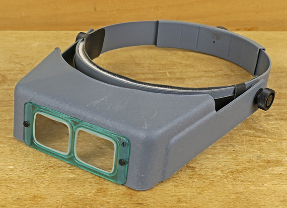
Let’s look at Donegan Optivisors, excellent quality headband magnifiers available for about $35. The table on the Donegan website shows, for example, a DA-4 focuses at 10″ and magnifies 2X. As discussed earlier, ignore the 2X and pay attention to the 10″.
However, this lens will actually put most people at a working distance closer than 10″ because some additional power is added by your eyes (especially if you are young) and/or by your eyeglasses if you are older than about 45 years. Note: wear the headband magnifiers over your whatever glasses you normally use for woodworking.
Lots of things come into play here but, again, let’s keep it simple: that 10″ lens will actually enable most people to work at about 6-7″. Similarly, for most people, the #3 (14″) lens will work at about 8″, the #5 (8″) lens at 5-6″, and the #7 (6″) lens at 4-5″. The Optivisor itself takes up some space too.
Even simpler: your working distance with most of the headband magnifiers will usually be 2″-4″ closer than the inches listed in the table.
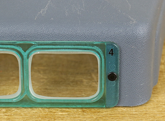
I use a #4/10″ lens and it probably will be your best bet too.
Technical stuff – you can skip it (but I can’t)
The number 4, which is also the number on the lens, means 4 diopters. To approximately convert diopters to focal length in inches, divide 40 by the diopter number. So, 40/4 = 10″, 40/5 = 8″, etc. In making the estimates of the actual functional working distance, I’ve assumed an additional input of about 2 diopters, from accommodation, spectacle add, or both. If this makes any sense to you, then you’ll also know that this is obviously variable.
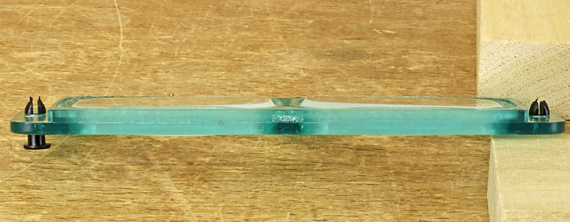
The Donegan lenses also incorporate another element. As your eyes focus closer, with or without optical aids, they must also converge more. This can be tiring or impossible depending on the circumstances. The Donegan lenses have the appropriate prism built in to compensate for this. Again, if this makes any sense to you, so will the profile of the lenses shown in the photo below.
Caution
The lenses in the Donegan DA series are crown glass; those in the LX series are acrylic. I would not rely on either of these for eye protection. They are no match for the impact resistance of polycarbonate, the material in protective eyewear.
Special for people with high myopia (nearsightedness)
You know who you are. When you remove your glasses or contact lenses with prescriptions of at least -4.00, you see very poorly far away and things only come into focus when they are very close to you.
You have a big advantage over the rest of us! To the extent that you are myopic, you can remove your corrective lenses and focus very close on your own. You probably don’t need the headband magnifiers and in fact, they may make the working distance impractically close.
Don’t forget this
There are countless exceptions and special circumstances to anything dealing with human vision.
Take care of your tools – have your eyes checked regularly.