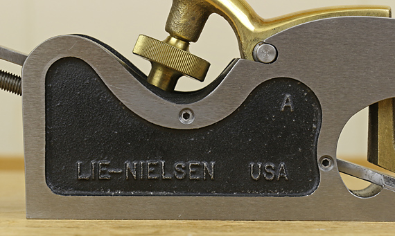
Since I cannot have my dream shoulder plane with all of the nifty features discussed in the previous post, an easy, helpful modification to my shoulder planes was in order: set screws in the style of the Veritas shoulder plane.
First, I marked the blade position on the sides of the body, and within that, locations for the screws on flat areas. I drilled and tapped for #8-32 screws (#29 drill for 75% thread). On the Lie-Nielsen large shoulder plane, above, I ground the socket end of 1/4″-long screws to shorten them to 7/32″ because 3/16″-long screws were barely long enough for all situations.
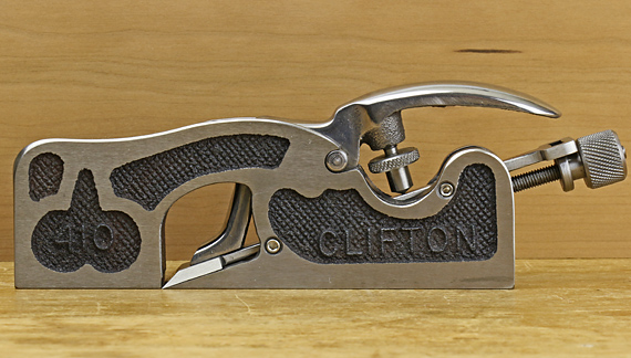
The 11/16″ x 5 5/16″ Clifton 410, below, which I have owned since before Lie-Nielsen made their similarly sized shoulder plane, is shown below with the set screws added. The 18° bed is sufficiently resistant to deflection, on par with the L-N.

On the Clifton, there is less room to fit the #8-32 screws into flat areas on the body, so I put the higher pair of screws to the rear of the lever cap wheel. They barely cleared the blade bed there, so it probably would have been better to instead put screws forward of the wheel where there is no blade bed to interfere. #6-32 screws would probably have been easier to install but the #8-32 x 3/16″ screws work well as they are.
In use, I have been finding it easiest to approximately set the lateral position and angle of the blade with the lever cap lightly clamped. Then I adjust the lower two screws, one on each side, to barely meet the blade. The screws themselves can then be used to fine-tune the blade position. Next, I advance the two higher screws to barely touch the blade. Then I adjust the cutting depth and snug the lever cap wheel. Note that the set screws may need to be backed off, just a trace, to adjust the cutting depth.
The set screws have proven to be helpful in setting and maintaining the blade position in these shoulder planes.


Really neat idea. Simple and functional.