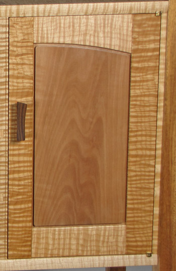
This continues the frame and panel construction. So far, the panel template has been made, and now we must position and size the grooves in the frame and coordinate this with the panel thickness.
Rout the grooves in the frame parts with a 3 or 4-wing slot cutter bit. Use the appropriate bearing diameter, which will ride the straight and curved parts, to create the desired depth of cut. Allow for seasonal movement when planning the depth of the grooves in the stiles. (A straight bit, standing the frame part on its side, would be fine to cut the grooves in a straight edge, and though passable for a shallow curve, it is not ideal.)
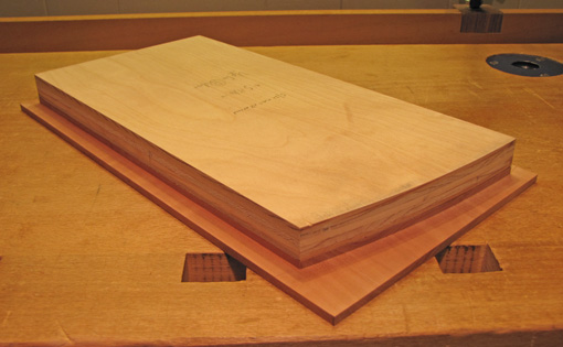
Position the template on the selected area of the panel stock and secure it with double-stick tape. The thickness of the panel stock will be determined by the frame thickness and the location of the groove. In sizing a frame and panel, remember that the strength is primarily in the frame.
For example, in a 5/8″ thick small door frame, it would be reasonable to use a 1/4″ wide groove, positioned in the middle of the frame width, and a 3/8+” thick panel, raised 1/8+”. This will leave the face of the panel about 1/32″ below the level of the frame which will allow for finish planing or sanding the frame after glue up. The panel, of course, is finished before glue up.
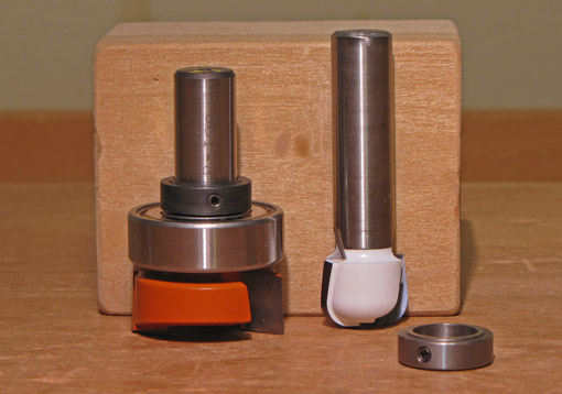
Raise the panel by hand-held routing with a square edge dado/planer bit or a short-radius bowl-and-tray bit which leave a smooth finish. These use a top bearing and have a short cutting length (1/4″ to ½”) to avoid the need for a template thicker than 3/4″. Examples of these types of bits are shown in the photo above. Adjust the depth of cut to yield the desired thickness in the panel edge. You are routing an outside curve, so go counter-clockwise (as viewed from above), cross grain first, and make the cut in two or more steps as needed. (I will not advocate climb cutting but I will do it for a final pass if the grain direction demands it.)
The result of the cut is shown in the photo in the previous post.
For a square-profile field, I round the corners. I pin the panel at the center of its width on the rails, from the back, with brass escutcheon pins and nip off the excess and file it flush.
My method suits my designs – the beauty is in simplicity and the wood but with a degree of design flair. The frame members have plain edges and the field profile is simple. The curve in the rail can be created without a template or router, even freehand, because the panel template is made directly from the actual frame.
By contrast, curved-edge frame and panel work with a sticking profile on the edges of the frame and an elaborate profile around the field of the panel usually involves a pair of offset templates, one for the rail, another for the panel. Bearing-guided router bits create the rail edge and a fearsome horizontal raised panel bit creates the edge of the panel’s field.
In summary, this method is another approach to a traditional construction – the frame and panel – that is suited for clean, simple designs with the added interest of the curved edge. The method is direct and it works.
